Monday, May 6, 2019

Router & It's Component


What is Router?
A router is a device that analyzes the contents of data packets transmitted within a network or to another network. We are going to focus on routers here since that's the reason you clicked on this page. Cisco has several different routers, among them are the popular 880 series, 2900 series and 3900 series.


The basic components of any Cisco router are:

Interfaces
The Processor (CPU)
Internetwork Operating System (IOS)
RX-Boot Image
RAM
NVRAM
ROM
Flash memory
Configuration Register

INTERFACES

These allow us to use the router! The interfaces are the various serial ports or ethernet ports which we use to connect the router to our LAN. There are several different interfaces, but we are going to hit the basic stuff only.

THE PROCESSOR (CPU)

All Cisco routers have a main processor that takes care of the main functions of the router. The CPU generates interrupts (IRQ) in order to communicate with the other electronic components in the router. The Cisco routers utilize Motorola RISC processors. Usually the CPU utilization on a normal router wouldn't exceed 20%.

THE IOS

The IOS is the main operating system on which the router runs. The IOS is loaded upon the router's bootup. It usually is around 2 to 5MB in size but can be a lot larger depending on the router series. The IOS is currently on version 12, and Cisco periodically releases minor versions every couple of months e.g. 12.1, 12.3 etc. to fix small bugs and add extra functionality.

THE RX-BOOT IMAGE

The RX-Boot image (also known as Boot-loader) is nothing more than a "cut-down" version of the IOS located in the router's ROM (Read Only Memory). If you had no Flash card to load the IOS from, you can configure the router to load the RX-Boot image, which would give you the ability to perform minor maintenance operations and bring various interfaces up or down. 


THE RAM

The RAM, or Random-Access Memory, is where the router loads the IOS and the configuration file. It works the same way as your computer's memory, where the operating system loads along with all the various programs. The amount of RAM your router needs is subject to the size of the IOS image and configuration file you have. To give you an indication of the amounts of RAM we are talking about, in most cases, smaller routers (up to the 1600 series) are happy with 12 to 16 MB while the bigger routers with larger IOS images would need around 32 to 64 MB of memory. Routing tables are also stored in the system's RAM.

THE NVRAM (NON-VOLATILE RAM)

The NVRAM is a special memory place where the router holds its configuration. When you configure a router and then save the configuration, it is stored in the NVRAM. This memory is not big at all when compared with the system's RAM. On a Cisco 1600 series, it is only 8 KB while on bigger routers, like the 2600 series, it is 32 KB. Normally, when a router starts up, after it loads the IOS image it will look into the NVRAM and load the configuration file in order to configure the router. The NVRAM is not erased when the router is reloaded or even switched off.

ROM (READ ONLY MEMORY)

The ROM is used to start and maintain the router. It contains some code, like the Bootstrap and POST, which helps the router do some basic tests and bootup when it's powered on or reloaded. You cannot alter any of the code in this memory as it has been set from the factory and is Read Only.
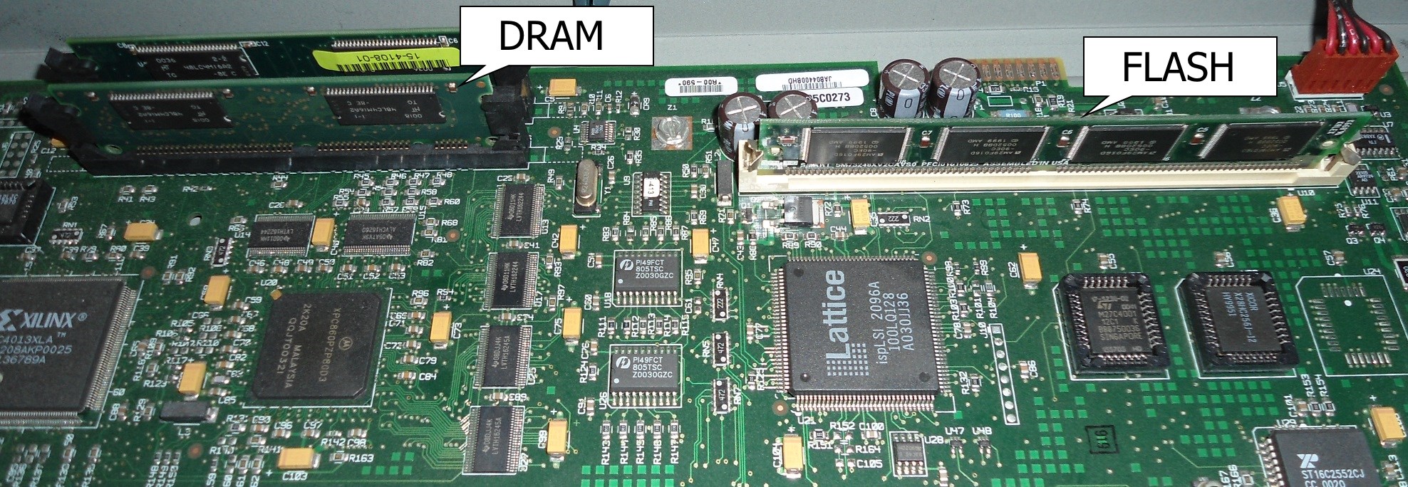

FLASH MEMORY

The Flash memory is that card I spoke about in the IOS section. All it is, is an EEPROM (Electrical Erasable Programmable Read Only Memory) card. It fits into a special slot normally located at the back of the router and contains nothing more than the IOS image(s). You can write to it or delete its contents from the router's console. Usually it comes in sizes of 4MB for the smaller routers (1600 series) and goes up from there depending on the router model.

CONFIGURATION REGISTER

Keeping things simple, the Configuration Register determines if the router is going to boot the IOS image from its Flash, TFTP server or just load the RX-Boot image. This register is a 16 Bit register, in other words has 16 zeros or ones. A sample of it in Hex would be the following: 0x2102 and in binary is: 0010 0001 0000 0010.

Tuesday, April 23, 2019

IP


What is IP (Internet Protocol)?
An Internet Protocol (IP) address is a number which assigned to each device connected to a computer network that uses the Internet Protocol for communication.

Two types of IP version mainly use one is IP version 4 or (IPv4) and IP version 6 or (IPv6).

What is IPv4 (Internet Protocol Version 4)?

Internet Protocol version 4 (IPv4) is the fourth version in the development of the Internet Protocol (IP) and the first version of the protocol to be widely deployed. IPv4 is described in IETF publication RFC 791 (September 1981), replacing an earlier definition (RFC 760, January 1980).

An IP address in IPv4 is 32-bits in size, which limits the address space to 4294967296 (232) IP addresses. IPv4 addresses are usually represented in dot-decimal notation, consisting of four decimal numbers, each ranging from 0 to 255, separated by dots, e.g., 172.16.254.1. Each part represents a group of 8 bits (octet) of the address.
The first octet referred here is the left most of all. The octets numbered as follows depicting dotted decimal notation of IP Address:


The number of networks and the number of hosts per class can be derived by this formula:


When calculating hosts' IP addresses, 2 IP addresses are decreased because they cannot be assigned to hosts, i.e. the first IP of a network is network number and the last IP is reserved for Broadcast IP.

Class A Address

The first bit of the first octet is always set to 0 (zero). Thus, the first octet ranges from 1 – 127, i.e. Class A addresses only include IP starting from 1.x.x.x to 126.x.x.x only. The IP range 127.x.x.x is reserved for loopback IP addresses. The default subnet mask for Class A IP address is 255.0.0.0 which implies that Class A addressing can have 126 networks (27-2) and 16777214 hosts (224-2).Class A IP address format is N.H.H.H.

Class B Address

An IP address which belongs to Class B IP Addresses range from 128.0.x.x to 191.255.x.x. The default subnet mask for Class B is 255.255.x.x. Class B has 16384 (214) Network addresses and 65534 (216-2) Host addresses. Class B IP address format is N.N.H.H.
 
Class C Address

The first octet of Class C IP addresses ranges from 192.0.0.x to 223.255.255.x. The default subnet mask for Class C is 255.255.255.x. Class C gives 2097152 (221) Network addresses and 254 (28-2) Host addresses. Class C IP address format is N.N.N.H.

Class D Address

Very first four bits of the first octet in Class D has IP address rage from 224.0.0.0 to 239.255.255.255. Class D is reserved for Multicasting. In multicasting data is not destined for a host, that is why there is no need to extract host address from the IP address, and Class D does not have any subnet mask.

Class E Address

This IP Class is reserved for experimental purposes only for R&D or Study. IP addresses in this class ranges from 240.0.0.0 to 255.255.255.254. Like Class D, this class too is not equipped with any subnet mask.

What is IPv6 (Internet Protocol Version 6)?

In IPv6, the address size was increased from 32 bits in IPv4 to 128 bits or 16 octets, thus providing up to 2128 (approximately 3.403×1038) addresses. This is deemed sufficient for the foreseeable future.

Address Structure

An IPv6 address is made of 128 bits divided into eight 16-bits blocks. Each block is then converted into 4-digit Hexadecimal numbers separated by colon symbols.
For example, given below is a 128 bit IPv6 address represented in binary format and divided into eight 16-bits blocks:

0010000000000001 0000000000000000 0011001000111000 1101111111100001 0000000001100011 0000000000000000 0000000000000000 1111111011111011

Each block is then converted into Hexadecimal and separated by ‘:’ symbol:
2001:0000:3238:DFE1:0063:0000:0000:FEFB
Even after converting into Hexadecimal format, IPv6 address remains long.

Global Unicast Address

This address type is equivalent to IPv4’s public address. Global Unicast addresses in IPv6 are globally identifiable and uniquely addressable.


[Image: Global Unicast Address] Global Routing Prefix: The most significant 48-bits are designated as Global Routing Prefix which is assigned to specific autonomous system. The three most significant bits of Global Routing Prefix is always set to 001.

Link-Local Address

Auto-configured IPv6 address is known as Link-Local address. This address always starts with FE80. The first 16 bits of link-local address is always set to 1111 1110 1000 0000 (FE80). The next 48-bits are set to 0, thus:


[Image: Link-Local Address Link-local addresses are used for communication among IPv6 hosts on a link (broadcast segment) only. These addresses are not routable, so a Router never forwards these addresses outside the link.

Unique-Local Address

This type of IPv6 address is globally unique, but it should be used in local communication. The second half of this address contain Interface ID and the first half is divided among Prefix, Local Bit, Global ID and Subnet ID.


[Image: Unique-Local Address] Prefix is always set to 1111 110. L bit, is set to 1 if the address is locally assigned. So far, the meaning of L bit to 0 is not defined. Therefore, Unique Local IPv6 address always starts with ‘FD’.

Scope of IPv6 Unicast Addresses:
[Image: IPv6 Unicast Address Scope] The scope of Link-local address is limited to the segment. Unique Local Address are locally global, but are not routed over the Internet, limiting their scope to an organization’s boundary. Global Unicast addresses are globally unique and recognizable. They shall make the essence of Internet addressing.

Sunday, April 21, 2019

Network Topologies


What do you mean by Network Topology?

Network topology is the arrangement of nodes. The topology of the network, and the relative locations of the source and destination of traffic flows on the network, determine the optimum path for each flow and the extent to which redundant options for routing exist in the event of a failure. There are two ways of defining network geometry: the physical topology and the logical (or signal) topology.

What is Physical Topology?

The actual layout of the computers, cables and other network devices which is connected physically.

What is Logical Topology?

The way in which the network appears to the devices that use it, or the way devices are communicating with each other.

What is Bus Topology?

It Uses a trunk or backbone to which all the computers on the network connect. Systems connect to this backbone using T connectors or taps. Coaxial cablings (10Base-2, 10Base5) were popular options years ago.

Advantages:

Cheap and easy to implement.
Require less cable.
Does not use any specialized network equipment.

Disadvantages:

Network disruption when computers are added or removed.
A break in the cable will prevent all systems from accessing the network.
Difficult to troubleshoot.

What is Ring Topology?

Logical ring means to say that data travels in circular fashion from one computer to another on the network. Ex - FDDI, SONET or Token Ring. Ring networks are most commonly wired in a star configuration. Token Ring has multi-station access unit (MSAU), equivalent to hub or switch. MSAU performs the token circulation internally.

Advantages:

Ring networks are moderately easy to Install.
Cable faults are easily located, making troubleshooting easier.
Disadvantages:

A single break in the cable can disrupt the entire network.
Expansion to the network can cause network disruption.

What is Star Topology?

All computers/devices connect to a central device called hub or switch. Each device requires a single cable point-to-point connection between the device and hub. It is implemented most widely.

Advantages:
Easy to troubleshoot and isolate problems.
Cable failure affects only a single user.
Easily expanded without disruption.

Disadvantages:
Requires more cable to the network
More difficult to implement
A central connecting device allows for a single point of failure

What is Mesh Topology?

Each computer connects to every other. High level of redundancy. This topology is used rarely. In this topology wiring is very complicated and cabling cost is high. Troubleshooting a failed cable is tricky. A variation hybrid mesh can create point to point connection between specific network devices, often seen in WAN implementation.

Advantages:

The network can be expanded without disruption to current uses.
Provides redundant paths between devices.
Disadvantages:

Complicated implementation.
Requires more cable than the other LAN topologies.

 
What is Wireless Networking?

It does not require physical cabling, particularly useful for remote access for laptop users. Eliminate cable faults and cable breaks and signal interference and security issue.

Advantages:

Network can be expanded without disruption to current users.
Allows for wireless remote access.
Disadvantages:

Limited speed in comparison to other network topologies.
Potential security issues associated with wireless transmissions.

What is FDDI?

Fiber Distributed Data Interface (FDDI) standard was developed by American National Standards Institute (ANSI). Dual ring technology for fault tolerance and it has speed of 100Mbps or higher. Media: fiber optic cable, > 2 kilometers. Also possible use copper wire as Copper Distributed Data Interface (CDDI). Access method is token-passing access method.

Sunday, April 14, 2019

Transmission Media


What is Coaxial Cable? 
It is used by cable operators but sometimes ago it also used by telephone companies. Coaxial cable is a type of cable that has an inner conductor surrounded by an insulating layer, surrounded by a conductive shielding. Many also have an insulating outer jacket the diagram below illustrates the construction of a typical cable. Electrical signal flows through the center conductor.


Table. Common coaxial cable types and uses. There are many additional RG designations, as well as variations within each number class. 


Cable type
Ω
Use
RG-6
75
Video, TV
RG-8
50
Radio, computer
RG-11
75
Long runs
RG-58
50
Radio, computer
RG-59
75
Video, TV
 

Advantages:

1. Coaxial cable can support greater cable lengths between network devices than twisted pair cable.
2. Thick coaxial cable has an extra protective plastic cover that help keep moisture away and stronger.

Disadvantages:

1. Thick coaxial is not bend easily so, it is difficult to install.
2. Difficult to troubleshoot a simple issue.


What is Twisted Pair Cable?


Twisted pair cable consists of a pair of insulated wires twisted together. It is a cable type used in telecommunication for very long time. Cable twisting helps to reduce noise pickup from outside sources and cross-talk on multi-pair cables.
The most commonly used form of twisted pair is unshielded twisted pair (UTP). It is just two insulated wires twisted together. any data communication cables and normal telephone cables are this type. Shielded twisted pair (STP) differs from UTP in that it has a foil jacket that helps prevent cross-talk and noise from outside source. In data communications there is a cable type called FTP (foil shielded pairs) which consists of four twisted pair inside one common shield (made of aluminum foil). The following are the cable types specified in ANSI/TIA/EIA which are mention below:


Category 1: Cat 1 cable was originally designed for voice telephony only, but thanks to some new techniques, long-range Ethernet and DSL, operating at 10Mbps and even faster, can be deployed over Cat 1.

Category 2: Cat 2 cable can accommodate up to 4Mbps and is associated with token-ring LANs.

Category 3: Cat 3 cable operates over a bandwidth of 16MHz on UTP and supports up to 10Mbps over a range of 330 feet (100 m). Key LAN applications include 10Mbps Ethernet and 4Mbps token-ring LANs.

Category 4: Cat 4 cable operates over a bandwidth of 20MHz on UTP and can carry up to 16Mbps over a range of 330 feet (100 m). The key LAN application is 16Mbps token ring.

Category 5: Cat 5 cable operates over a bandwidth of 100MHz on UTP and can handle up to 100Mbps over a range of 330 feet (100m). Cat 5 cable is typically used for Ethernet networks running at 10Mbps or 100Mbps. Key LAN applications include 100BASE-TX, ATM, CDDI, and 1000BASE-T. It is no longer supported, having been replaced by Cat 5e.

Category 5e: Cat 5e (enhanced) operates over a bandwidth of 100MHz on UTP, with a range of 330 feet (100 m). The key LAN application is 1000BASE-T. The Cat 5e standard is largely the same as Category 5, except that it is made to somewhat more stringent standards. Category 5e is recommended for all new installations and was designed for transmission speeds of up to 1Gbps (Gigabit Ethernet). Although Cat 5e can support Gigabit Ethernet, it is not currently certified to do so.

Category 6: Cat 6, specified under ANSI/TIA/EIA-568-B.2-1, operates over a bandwidth of up to 400MHz and supports up to 1Gbps over a range of 330 feet (100 m). It is a cable standard for Gigabit Ethernet and other network protocols that is backward compatible with the Cat 5/5e and Cat 3 cable standards. Cat 6 features more stringent specifications for crosstalk and system noise. Cat 6 is suitable for 10BASE-T/100BASE-TX and 1000BASE-T (Gigabit Ethernet) connections.

Category 7: Cat 7 is specified in the frequency range of 1MHz to 600MHz. ISO/IEC11801:2002 Category 7/Class F is a cable is based on four twisted copper pairs, features even more stringent specifications for crosstalk and system noise than Cat 6.

Advantages: 

1. Cheaper and far easier to splice
2. Less susceptible to electrical interference caused by nearby equipment or wires.
3. In turn are less likely to cause interference themselves.
4. Because it is electrically "cleaner", STP wire can carry data at a faster speed.

Disadvantages: 

1. STP wire is that it is physically larger and more expensive than twisted pair
wire.
2. STP is more difficult to connect to a terminating block.


What is Fiber Optic or Optical fiber Cable?


A fiber optic cable is a network cable that contains strands of glass fibers inside an insulated casing. They're designed for long distance, very high-performance data networking and telecommunications.
Compared to wired cables, fiber optic cables provide higher bandwidth and can transmit data over longer distances. Fiber optic cables support much of the world's internet, cable television and telephone systems.

Advantages:

1. One single mode fiber can replace a metal of time larger and heavier.
2. Multi-mode optical cable has a larger diameter and can be used to carry signal
over short distance.

Disadvantages:

1. Fiber optic versus metal cable is that it is difficult to make connections to
fiber optic cable.
2. The optical fiber must be highly polished to allow light to pass with little loss. 

Thursday, April 11, 2019

Terminology of Networking


Basic Terminology of Networking

Computers on a network typically fall into one of three roles. Usually a computer is considered either a workstation (sometimes referred to as a client), server, or a peer.

What is Workstation? 

These are computers that use network resources, but that do not host resources of their own. For example, a computer that is running Windows XP would be considered a workstation so long as it is connected to a network and is not sharing files or printers.

What is Server?

These are computers that are dedicated to the task of hosting network resources. Typically, nobody is going to be sitting down at a server to do their work. Windows servers (that is, computers running Windows Server 2003, Windows 2000 Server, or Windows NT Server) have a user interface that is very similar to what you would find on a Windows workstation. It is possible that someone with an appropriate set of permissions could sit down at the server and run Microsoft Office or some other application. Even so, such behavior is strongly discouraged because it undermines the server’s security, decreases the server’s performance, and has the potential to affect the server’s stability.
A domain, in the context of networking, refers to any group of users, workstations, devices, printers, computers and database servers that share different types of data via network resources. There are also many types of subdomains. 

What is Peer-to-Peer network?

In its simplest form, a peer-to-peer connection means a device connected with another device directly. However, a peer-to-peer (P2P) network is created when two or more PCs are connected and share resources without going through a separate server computer. A P2P network can be an ad hoc connection—a couple of computers connected via a Universal Serial Bus to transfer files. A P2P network also can be a permanent infrastructure that links a half-dozen computers in a small office over copper wires. Or a P2P network can be a network on a much grander scale in which special protocols and applications set up direct relationships among users over the Internet.
The initial use of P2P networks in business followed the deployment in the early 1980s of free-standing PCs. In contrast to the mini mainframes of the day, such as the VS system from Wang Laboratories Inc., which served up word processing and other applications to dumb terminals from a central computer and stored files on a central hard drive, the then-new PCs had self-contained hard drives and built-in CPUs. The smart boxes also had onboard applications, which meant they could be deployed to desktops and be useful without an umbilical cord linking them to a mainframe.

 
What is the difference between host and node?

Host: For companies or individuals with a Web site, a host is a computer with a Web server that serves the pages for one or more Web sites. A host can also be the company that provides that service, which is known as hosting.
Node: In a network, a node is a connection point, either a redistribution point or an end point for data transmissions. In general, a node has programmed or engineered capability to recognize and process or forward transmissions to other nodes.
In short both are similar with a little difference, Host is something which offers services to other nodes connected in a network. Example: Server (all servers are host, but not all hosts are severs). Node is a device which participate in the networking connection for forwarding of packets.


Wednesday, April 10, 2019

OSI Model


What is Open Systems Interconnection model?

(OSI model) is a conceptual model that characterizes and standardizes the communication functions of a telecommunication or computing system without regard to their underlying internal structure and technology. Its goal is the interoperability of diverse communication systems with standard protocols. The model partitions a communication system into abstraction layers. The original version of the model defined seven layers.


Layer 1 Physical Layer

It conveys the bit stream to electrical impulse, light or radio signal through the network at the electrical and mechanical level. It provides the hardware means of sending and receiving data on a carrier, including defining cables, cards and physical aspects. Fast Ethernet, RS232, and ATM are protocols with physical layer components.

 
Layer 2 Data Link Layer

At OSI Model, Layer 2, data packets are encoded and decoded into bits. It furnishes transmission protocol knowledge and management and handles errors in the physical layer, flow control and frame synchronization. The data link layer is divided into two sub layers: The Media Access Control (MAC) layer and the Logical Link Control (LLC) layer. The MAC sub layer controls how a computer on the network gains access to the data and permission to transmit it. The LLC layer controls frame synchronization and flow control. The FCS (Frequency Check Sequence) extra error-detecting code added to a frame in a communications protocol.
 
Layer 3 Network Layer

Layer 3 provides switching and routing technologies, creating logical paths, known as virtual circuits, for transmitting data from node to node. Routing and forwarding are functions of this layer, as well as addressing, internetworking, error handling, congestion control and packet sequencing.
 
Layer 4 Transport Layer

OSI Model, Layer 4, provides transparent transfer of data between end systems, or hosts, and is responsible for end-to-end error recovery and flow control. It ensures complete data transfer.


Layer 5 Session Layer

This layer establishes, manages and terminates connections between applications. The session layer sets up, coordinates, and terminates conversations, exchanges, and dialogues between the applications at each end. It deals with session and connection coordination.
 
Layer 6 Presentation Layer

This layer provides independence from differences in data representation (e.g., encryption) by translating from application to network format, and vice versa. The presentation layer works to transform data into the form that the application layer can accept. This layer formats and encrypts data to be sent across a network, providing freedom from compatibility problems. It is sometimes called the syntax layer.
 
Layer 7 Application Layer

OSI Model, Layer 7, supports application and end-user processes. Communication partners are identified, quality of service is identified, user authentication and privacy are considered, and any constraints on data syntax are identified. Everything at this layer is application-specific. This layer provides application services for file transfers, e-mail, and other network software services. Telnet and FTP are applications that exist entirely in the application level. Tiered application architectures are part of this layer.


Tuesday, April 2, 2019

What is Computer Networking?


What is a Network?
A network consists of two or more computers that are linked in order to share resources (such as printers and CDs), exchange files, or allow electronic communications. The computers on a network may be linked through cables, telephone lines, radio waves, satellites, or infrared light beams.
Two very common types of networks include:
  • Local Area Network (LAN)
  • Metropolitan Area Networks (MAN)
  • Wide Area Network (WAN)
You may also see references to a Metropolitan Area Networks (MAN), a Wireless LAN (WLAN), or a Wireless WAN (WWAN). 

Local Area Network 
A Local Area Network (LAN) is a network that is confined to a relatively small area. It is generally limited to a geographic area such as a writing lab, school, or building.
Computers connected to a network are broadly categorized as servers or workstations. Servers are generally not used by humans directly, but rather run continuously to provide "services" to the other computers (and their human users) on the network. Services provided can include printing and faxing, software hosting, file storage and sharing, messaging, data storage and retrieval, complete access control (security) for the network's resources, and many others.
Workstations are called such because they typically do have a human user which interacts with the network through them. Workstations were traditionally considered a desktop, consisting of a computer, keyboard, display, and mouse, or a laptop, with with integrated keyboard, display, and touch pad. With the advent of the tablet computer, and the touch screen devices such as iPad and iPhone, our definition of workstation is quickly evolving to include those devices, because of their ability to interact with the network and utilize network services.
Servers tend to be more powerful than workstations, although configurations are guided by needs. For example, a group of servers might be located in a secure area, away from humans, and only accessed through the network. In such cases, it would be common for the servers to operate without a dedicated display or keyboard. However, the size and speed of the server's processor(s), hard drive, and main memory might add dramatically to the cost of the system. On the other hand, a workstation might not need as much storage or working memory, but might require an expensive display to accommodate the needs of its user. Every computer on a network should be appropriately configured for its use.
On a single LAN, computers and servers may be connected by cables or wirelessly. Wireless access to a wired network is made possible by wireless access points (WAPs). These WAP devices provide a bridge between computers and networks. A typical WAP might have the theoretical capacity to connect hundreds or even thousands of wireless users to a network, although practical capacity might be far less.
Nearly always servers will be connected by cables to the network, because the cable connections remain the fastest. Workstations which are stationary (desktops) are also usually connected by a cable to the network, although the cost of wireless adapters has dropped to the point that, when installing workstations in an existing facility with inadequate wiring, it can be easier and less expensive to use wireless for a desktop.
See the Topology, Cabling, and Hardware sections of this tutorial for more information on the configuration of a LAN. 


Metropolitan Area Network
A metropolitan area network is a computer network that interconnects users with computer resources in a geographic area or region larger than that covered by even a large local area network but smaller than the area covered by a wide area network.
 
Wide Area Network
Wide Area Networks (WANs) connect networks in larger geographic areas, such as Florida, the United States, or the world. Dedicated transoceanic cabling or satellite uplinks may be used to connect this type of global network.
Using a WAN, schools in Florida can communicate with places like Tokyo in a matter of seconds, without paying enormous phone bills. Two users a half-world apart with workstations equipped with microphones and a webcams might teleconference in real time. A WAN is complicated. It uses multiplexers, bridges, and routers to connect local and metropolitan networks to global communications networks like the Internet. To users, however, a WAN will not appear to be much different than a LAN.
Network t0pologies and types of networks
The term network topology describes the relationship of connected devices in terms of a geometric graph. Devices are represented as vertices, and their connections are represented as edges on the graph. It describes how many connections each device has, in what order, and what sort of hierarchy.
Typical network configurations include the bus topology, mesh topology, ring topology, star topology, tree topology and hybrid topology.
Most home networks are configured in a tree topology that is connected to the Internet. Corporate networks often use tree t0pologies, but they typically incorporate star topology and an Intranet.


What was the first computer network?
One of the first computer networks to use packet switching, ARPANET was developed in the mid-1960s and is considering to be the direct predecessor of the modern Internet. The first ARPANET message was sent on October 29, 1969.